Pages

Sunday 16 February 2014

How To Program ATmega Microcontrollers Using Parallel Port In Linux

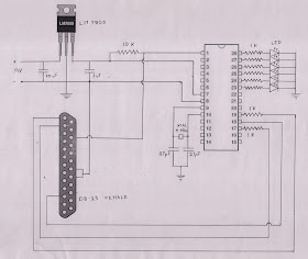
Parallel Port Programmer for ATmega8 is a simple circuit that can be made at home. Parallel Port Programmer Circuit is as shown below. 

Circuit Diagram
Parallel port programming atmega microcontroller in ubuntu


Components Required
9V Battery                     - 1
7805 Voltage Regulator   - 1
ATmega8                       - 1
DB-25 Female                - 1
Crystal Oscillator 4MHz  - 1
Resistor 10K                  - 1
Resistor 1K                    - 8
Capacitor 27pF               - 2
Capacitor 10uf                - 1
Capacitor 1 uf                 - 1

Softwares To Be Installed

1. avr-libc
2. binutils-avr
3. avrdude
4. gcc
5. gcc-avr
6. uisp

Software Installation
Now open your terminal and execute the following commands to install the softwares.
          
sudo apt-get install avr-libc binutils-avr avrdude gcc gcc-avr
sudo apt-get install uisp

Now create your first program.

Execute the following command to create the program file.

nano first.c

Now copy the following code to this file.

#include <avr/io.h>

#include <util/delay.h>

void sleep(uint8_t millisec)

{
while(millisec)
{
_delay_ms(1);/* 1 ms delay */
millisec--;
}
}

int main()

{
DDRC |=0b11111111;   //Declare PORT C as an output
while(1)
        
{
PORTC |=0b11111111;
PORTC &=0b00000000;  //turn off PORT C 
sleep(1000);

PORTC |=0b11111111;

PORTC &=0b11111111; //turn on PORT C
sleep(1000);
  }
return 1;
}

Next is to save the file. Press CTRL + O  to save the file. Now exit from the file. Press CTRL + X to exit from the file.

Next is to compile the code. Execute the following command to compile the code. Compiling will generate an object file.

avr-gcc -mmcu=atmega8 first.c -o first

Now generate the hex file from the object file. Execute the following command to generate the hex file.

avr-objcopy -O ihex first first.hex

Now upload the hex file to your microcontroller using the following command. Before executing the following command connect the programmer circuit to your parallel port.

sudo uisp -dprog=dapa -dpart=ATmega8 if=first.hex -dlpt=0x378 --erase --upload
Now you will get the following result in terminal. Then programming ATmega8 is successfull.

Tuesday 4 February 2014

How to Configure XBee RF Modules For Broadcast Mode Operation ?

Important : Please read this tutorial to get an idea about X-CTU basics and connecting XBee Radios to X-CTU.

Broadcast mode is a mode of operation in which any RF Module in the range can accept a packet that contains broadcast address. In this mode of operation, Receiver will not send ACK of RF packet reception to the Transmitter. Also the Transmitter will not resend the RF packet.


Configuring XBee RF Modules For Broadcast Mode Of Operation.

Step 1:  Read the configuration of XBee RF modules.
Step 2:  PAN ID should be same throughout the network.
Step 3:  Set DL of all the XBee RF modules to 0x0000FFFF.
Step 4:  Set DH of all the XBee RF modules to 0x00000000.
(No Need to enter 0x while programming the Module)


Sample Broadcast Network Configuration
Step 5. Now Write the new configuration to the XBee RF modules.
Step 6. Now open terminal Tab in Both X-CTU windows. Text typed in one terminal will be displayed in the other terminal instantaneously.

Important : If you have any doubts in connecting XBee Radios and Reading the XBee configuration, Refer this tutorial

Monday 3 February 2014

How to Configure XBee Modules For Unicast Mode Of Communication ?

Important : Please read this tutorial to get an idea about X-CTU basics and connecting XBee Radios to X-CTU.

Unicast mode is a mode in which the recieving module will send an ACK (acknowledgement) of RF packet reception to the transmitting module. If the transmitting module does not receive ACK, transmitter will send the signals upto three times or until the ACK is recieved. Unicast mode of operation can be done in two ways. short 16-bit addresses and Long 64-bit addresses.
Short 16-bit addresses

Step 1. Read the configuration of XBee RF modules.
Step 2. PAN ID should be same throughout the network.
Step 3. Set the Source Address to 16-bits by setting MY < 0xFFFE.
Step 4. Set DH=0 and DL < 0xFFFE to set the Destination Address to a 16-bit value.
Step 5. MY of Transmitter should match with the DL of Receiver and DL of Transmitter should match with  the MY of Receiver.

Sample Unicast network configuration using 16-bit addressing.

Step 6. Now Write the new configuration to the XBee RF modules.
Step 7. Now open terminal Tab in Both X-CTU windows.Text typed in one terminal will be displayed in the other terminal instantaneously.


Long 64-bit Addresses

Step 1. Read the configuration of XBee RF modules.
Step 2. PAN ID should be same throughout the network.
Step 3. Disable MY (MY = 0xFFFE or MY = 0xFFFF). When the MY parameter is disabled (MY = 0xFFFF or 0xFFFE), the module’s source address is set to the 64-bit IEEE address stored in the SH and SL parameters.
Step 4. Now set SH , SL , DH and DL of the Transmitter and Receiver in such a way that SL+SH of the Transmitter should match with the DL + DH of the Receiver. Also DL+DH of the Transmitter should match with the SL+SH of the Receiver ( SL+SH could not be changed. So DL+DH of one XBee Radio module have to be changed to match the SL+SH  of the other module). 

Sample Unicast network configuration using 64-bit addressing.
Step 5. Now Write the new configuration to the XBee RF modules.
Step 6. Now open terminal Tab in Both X-CTU windows. Text typed in one terminal will be displayed in the other terminal instantaneously.


Important : If you have any doubts in connecting XBee Radios and Reading the XBee configuration, Refer this tutorial